
Sheet Metal Fabrication: From Laser-Cut Blanks to a Welded, Powder-Coated Bracket
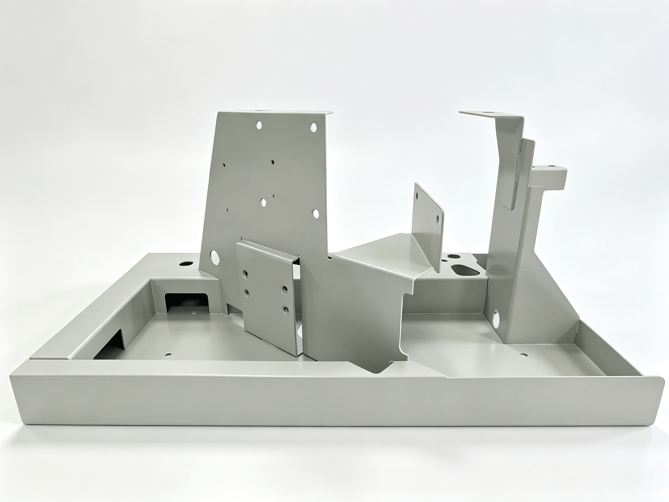
Sheet metal fabrication turns flat blanks into structural assemblies. The bracket below is that whole chain in one part: a formed pan with vertical plates welded inside it, a stepped support, and a stiffening ear — powder coated after welding, not before.
Cutting, forming, welding, hardware, and coating all happen under one roof; the order of operations is what makes the part work.
What decides the outcome
- Plate position. The vertical plates’ holes are toleranced to each other, not to their own outer edges — the welding fixture sets that, not the cut quality of one plate.
- Flatness after welding. A formed pan is stiff, but weld shrinkage pulls; tack sequence and weld direction control distortion, not more weld.
- Fit-up after coating. 60–120 µm of powder shifts every hole and mating face unless masking or allowance is planned up front.
Cutting and forming
Flat-pattern review comes first: holes stay 2.5 × t + inside radius off a bend line and 1.5 × t off an edge, and slivers that turn into burrs get designed out. We cut on a 6 kW fiber laser (3000 × 1500 mm sheets) with nitrogen assist on stainless and aluminum, for an oxide-free edge that helps both the weld and powder adhesion. Tolerance: ±0.2 mm.
A 320-ton CNC press brake with a 4000 mm bed forms four bends in the pan, each feeding into the position of the plate welded on top — so the flat pattern comes from the real tooling (V-die opening, inside radius, material-matched K-factor), not a generic bend deduction. Inside radius ≥ t, flange height ≥ 2 × t + R, repeatability ±0.5° and ±0.5 mm.
Welding without losing the datums
Most welded sheet metal assemblies fail here: every plate is right on its own and in the wrong place together.
- Tack first. Fixture the plates, tack every joint, and check critical holes before running a bead.
- Balance the heat. Weld symmetrically, alternate sides, and stitch or backstep long joints — welding one side of a pan end to end curls it.
- TIG where it shows, MIG where it carries, and spot welding for panels that must stay flat.
- Machine and measure after welding. Tight bores and threads belong after the heat, and a base plate that pulls is corrected before finishing, not after coating.
Hardware, coating, and inspection
PEM nuts, studs, and standoffs go in before coating, the pressed side dressed flat afterwards — anything fitted later scratches the finish and loads the coating in compression. Deburring matters the same way: a burr on the bend line becomes an angle deviation, and in a joint it holds the parts apart so the weld bridges the gap instead of fusing it.
Coating is a process, not a colour choice: degrease, blast or phosphate, apply electrostatically, cure to 60–120 µm, and mask threads, bores, and grounding pads on the drawing — tape and plugs are cheap, re-tapping a coated hole is not. Inside corners coat thinner, so add a radius where full coverage is needed; we flag it during powder coating review.
Inspection follows the function: first article with a dimensional report, critical hole positions and perpendicularity measured relative to each other, base flatness on a surface plate or Zeiss CMM, and coating thickness against the specified RAL.
One part, the whole chain
| Step | What we run | Typical capability |
|---|---|---|
| Fiber laser cutting | 6 kW, 3000 × 1500 mm sheets, nitrogen assist on stainless | ±0.2 mm |
| CNC press brake | 320 tons, 4000 mm bed | ±0.5° angle, ±0.5 mm flange |
| Sheet materials | Carbon steel 0.5–12 mm, stainless 0.5–8 mm, aluminum 0.5–6 mm | Per material |
| Welding | TIG, MIG, spot, robotic | Fixture-located |
| Hardware insertion | PEM nuts, studs, standoffs | Inserted before coating |
| Powder coating | RAL colours, gloss / matte / texture | 60–120 µm, masked threads |
| Prototype lead time | Quote with DFM feedback | 5–10 business days |
DFM checklist for welded sheet metal parts
- Send a flat pattern (DXF/DWG) and the 3D model with sheet metal features.
- Say whether critical tolerances apply before or after coating.
- Keep hole-to-bend ≥ 2.5 × t + R and hole-to-edge ≥ 1.5 × t.
- Keep inside radius ≥ t and flange height ≥ 2 × t + R.
- Flag faces that must stay conductive, threads that must stay clean, and bores to machine after welding.
- Tell us the load path — a 5 kg cover and a dynamic load look identical in 2D.
Send the assembly, not just the part
If the drawing is a welded assembly, send the assembly. We review weld access, fixture cost, masking, and inspection together, and quote with DFM notes within 24 hours. MOQ is one piece — the process that runs the prototype runs the production order. Upload your files.

